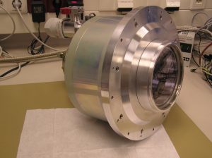
 The CCD system foreseen for the BMK is the PEPSI RED spare 10k×10k device. The detector is a monolithic STA1600LN device from STA. It is a thinned, backside illuminated 10560×10560-pixel solid-state CCD with a transparent poly-crystalline silicon gate structure for creating electron hole pairs. Its full frame is organized in two halves each containing an array of 10560 horizontal by 5280 vertical photosites. Horizontal transport registers along the top and bottom permit simultaneous readout of both halves. The pixel spacing is 9 μ × 9 μ .
For dark reference, each readout line is preceded by 8 dark pixels. This architecture provides video information as a single sequential readout of 5280 lines containing 1330 photosites. One output amplifier is located at the end of each horizontal register, thus, the device has in total 16 amplifiers. They are dual FET floating diffusion amplifiers with a reset MOSFET tied to the input gate. It was backside processed and characterized at ITL (Lesser 2012, SPIE 8453).
The device has been fully characterized (protocol serial number SN18043). Its flat field uniformity is good in the red where the AR coating has been optimized. However, uniformity is not very good below 500 nm due to features on the surface which appeared during backside etching. There are a significant number of bad columns (faintly bright or dark) in the device making it of lower grade than the PEPSI RED and BLUE CCDs.
The electrical performance is about the same as for the other devices. All 16 channels are operable. CTE appears excellent from cosmic ray analysis. Dark current is ≈ 2 e− per pixel per hour at the operating temperature of -90°C during testing. The median total system noise is about 4.5 e− rms (range 3.7–4.9 e−) with gain settings ranging between 0.48–0.60 e−/DN at 135 kHz read out. No significant glows are seen when the OD voltages are turned off during integration. Full well is approximately at 65,000 e−. Peak QE of 94% is reached at 670 nm and remains above 90% for 600–750 nm but drops to 85% at 550 nm and to 46% at 907 nm. Read-out time is 35s in the current DSP setting, frame transfer time is 9s, and CCD cleaning time is 4s. With 2s overhead, the full cycle time is 50s.
The large CCD size requires a special dewar. It was designed and manufactured at AIP. A diode protection circuit was designed and fabricated at ITL and installed in the dewar to reduce the possibility of damage from voltage spikes. The dewar has four vacuum connectors. Two of them are carrying the video signals (8 channels each). The third is connected to the clock signals and the fourth is for the temperature control. Therefore, the dewar requires a three-cable connection to the CCD controller (ARC-48C with two eight-port video-channel cards and one cable connection to the temperature controller (CryoCon Model 24C, from Cryogenic Control Systems, Inc.).
The CCD is run through software called AzCam. AzCam is a CCD image acquisition and analysis system developed at ITL. The system consists of three main components:
- the main server named AzCamServer,
- a camera server which interacts with the controller hardware named ControllerServer, and
- various client applications such as AzCamTool and AzCamConsole.
AzCamServer is the core program which coordinates all AzCam activities. It communicates over internet sockets with control clients, hardware servers, logging processes, etc. AzCamServer processes commands and interacts with the various software components as necessary, receiving image data, creating FITS image files, and sending image files to remote data processes. AzCamServer is written in Python with C++ components. ControllerServer communicates with AzCamServer over a socket and directly commands the controller hardware (a PCI-Express card) via drivers. ControllerServer is written entirely in C++. For local testing and debugging the user GUI is AzCamTool, which is a LabVIEW application. This client allows users to select image file names, binning, DSP code, and many other parameters.
